Passive electronics components
Passive components are devices designed to condition the electrical and electronic quantities without returning a gain, in practice they return on their output a value equal to or lower than that present at their input.
The passive components, usually, in an electrical or electronic circuit surround the active components, are used to condition the input and output signals and set the operating parameters of the stages that make up the circuit itself.
It should be noted that what has been said above is mainly valid in direct current, in alternating current it is not always the case, there are some conditions in which a circuit made up of passive components can have a resonance condition, i.e. the signal on a single frequency can have a value higher than that at its entry, but only on a frequency, the frequency of agreement in question is established by the value of the passive components, to find out more you can go to the radiowave page of this site.
The most commonly used passive components are resistors, capacitors and fuses.
The resistors are electronic components whose value is measured in Ω that serve (through the aptitude to be crossed or not by the current that depends on their value) to obtain at a given point of the circuit currents and voltages calculated in the design phase. Depending on the current that must cross them, they are available in various values and powers (and therefore container size)
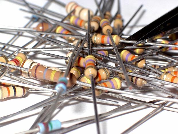
 1/4 Watt resistors
Electrical Symbol of the resistor
1/4 Watt resistors
Electrical Symbol of the resistor
To establish the value of the resistances the color code is used as shown in the image below, click on it to enlarge:
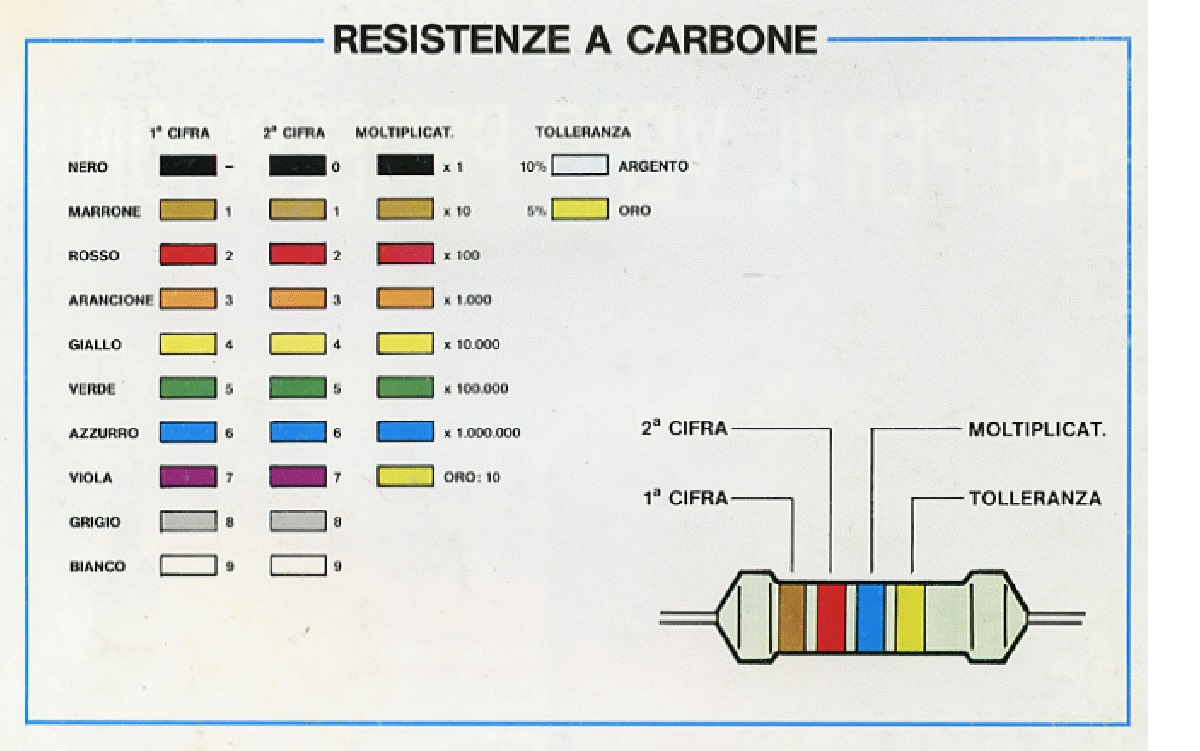
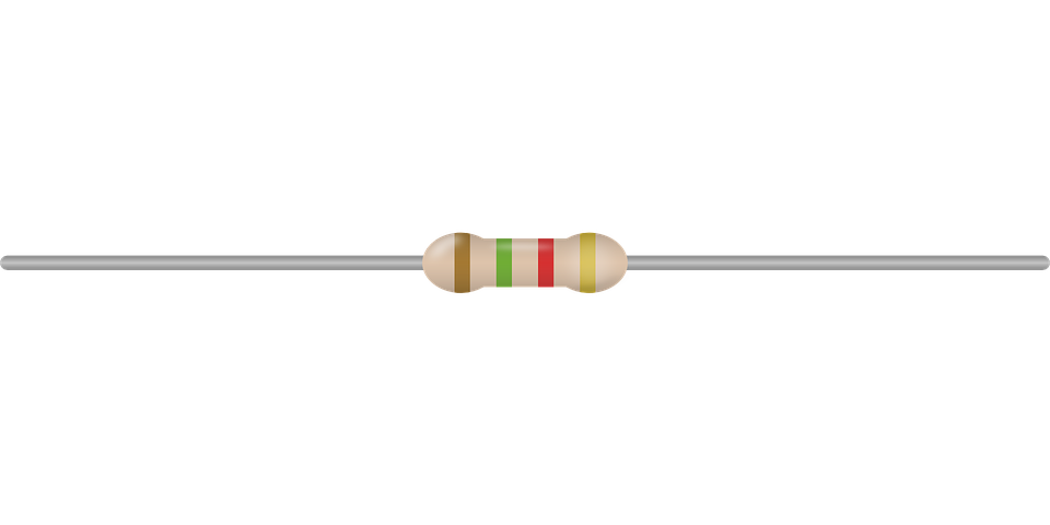
Resistor color code table resistor 1400Ω value with 5% tolerance
Using the code is simple, just look at the first two colors starting from the one closest to the rheophores (connection terminals) and add as many zeros as indicated by the multiplication coefficient represented by the third color.
Example, we have a resistance with the following colors. brown, black, red, we read this: looking at the table we see that the brown corresponds to the number 1, the black corresponds to the number 0, then we get the number 10, at this point seeing that the red corresponds to the number 2 we add two zeros and our number becomes 10 + two zeros = 1000 or 1000Ω.
The fourth color band represents the tolerance, that is how much you can move more or less the actual value of the resistor with respect to the nominal value, for example a 100Ω resistor with 5% tolerance can have a real value from 95Ω to 105Ω , the lack of the fourth colored band indicates a tolerance of 20% (resistors in disuse for many years).
There are high power resistors with ceramic body where the value and power are indicated directly by printing on the container.
Resistances are also manufactured whose value can be changed manually (rheostats and potentiometers), and automatic resistances (NTC and PTC sensitive to heat), for further information contact me by going to the "contacts" page.
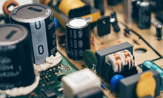
The capacitors or electrical capacitors are passive electronic components whose value is measured in Farad (symbol F, the submultiples pF and µF are used) consisting of two armatures with a dielectric in insulating material, they serve to store energy in the form of a field electrostatic to then return it when required, they are used in the circuits thanks to their properties of acting as a filter, decouplers, phase shifters or rephasing devices (because they introduce a delay in returning the stored signal) from transmission line tuners (see page radiowave) and to their property of blocking the direct current and passing only alternating currents (taking advantage of the capacitive reactance, that is the aptitude to be crossed by more intense currents as one increases in frequency).
There are various types of capacitors, the most important being electrolytics (used for large capacities), ceramics and polyester, the name is due to the composition of the dielectric (if polyester, it means that the dielectric is made of polyester material, if ceramic, with ceramic material), even air (with obvious limitations) can be used as dielectric. The maximum potential difference applicable to the condenser depends on the thickness of the dielectric, overcoming it a destructive event occurs for the component, i.e. the perforation or discharge through the dielectric that makes it unusable (short circuit), it is stamped on the container together with the capacity and indicated as V (Voltage max of work).
Manually variable value condensers are also manufactured (variable capacitors), for further information contact me by going to the "contacts" page
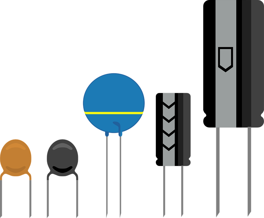
Ceramic and electrolytic capacitors Symbol used in electrical diagrams
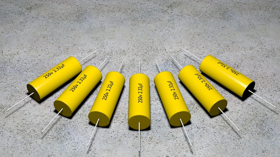
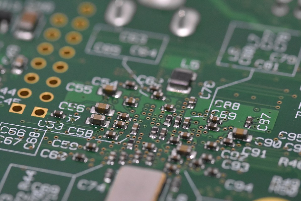
Polyester Capacitors Surface Mount Capacitors (SMD)
Understanding the value of the capacitors is not difficult, just understand the rule, as for the electrolytics you will find everything clearly stamped on the container including the polarity, because you have to be careful, the electrolytics are polarized components, you can not connect them at random, otherwise it happens the destruction of the component (explosion) which can also be dangerous if it is a high capacity capacitor.
For the ceramics capacitors, refer to the table available at this link.
For the polyester capacitors, refer to the table available at this link.
For surface mount chip (SMD) capacitors it is impossible to trace the value without resorting to the wiring diagram or capacitance meter.
The Fuses are components that protect electrical circuits, they are simple but important components, there is at least one fuse in each electrical or electronic device. Their function is to stop if the intensity of the current exceeds that established by the manufacturer of the device, in practice in the event of a short circuit or other malfunction that causes the current absorbed to rise to a dangerous level, the fuse stops and the circuit opens, so avoid overheating and fire. There are fast fuses (which are interrupted immediately), semi-retarded (slightly delayed at interruption) and delayed (there is a pre-set time before the interruption) in order to satisfy every need. Self-resetting fuses are also manufactured, but only for small currents.
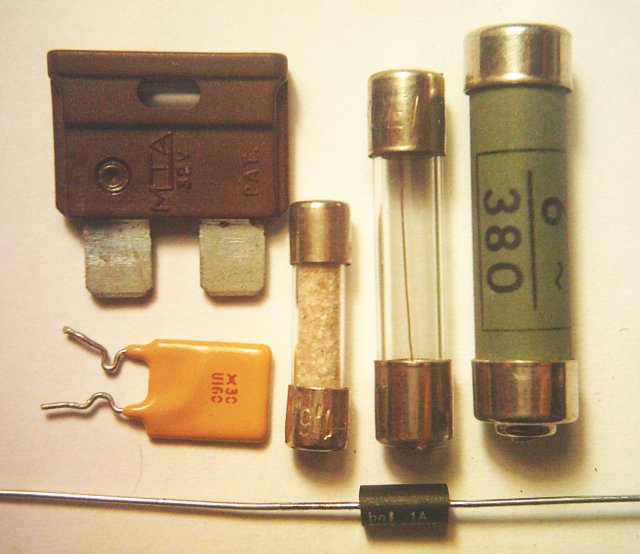
Various types of fuses Electrical symbol of the fuse
The value of the maximum current that can cross them and the applicable voltage is stamped directly on the fuse.
The passive components are not only those mentioned above, there are many others, among others we can mention:
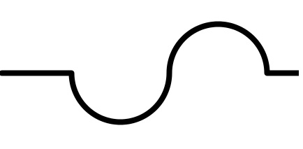
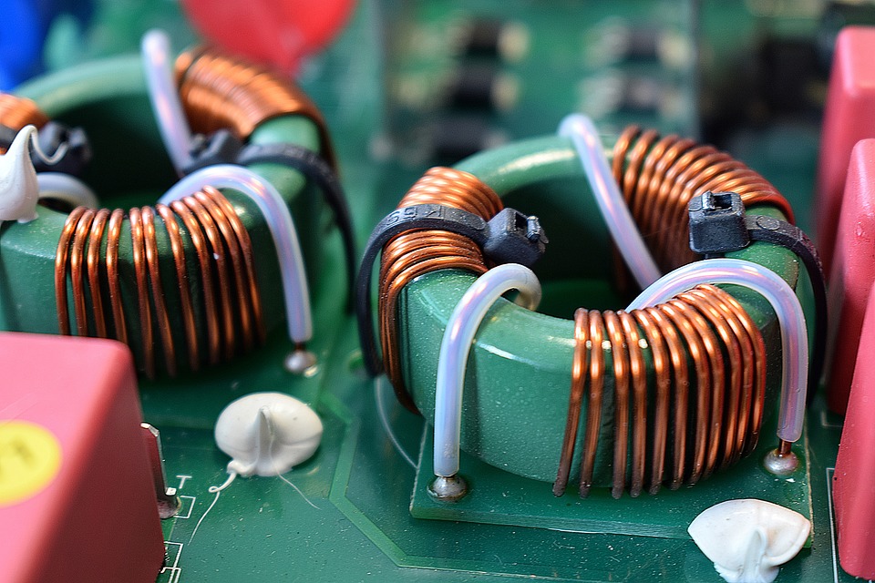
The inductance or coil, exploits the electrical property of the inductive reactance of having an increasing impedance as the frequency of the signal passing through it increases, is constituted by a solenoid wound on a plastic material or on a ferromagnetic core, it works only in the presence of alternating signals , its value is expressed in Henry (symbol H), in direct current it is nothing more than a wire having a minimum capacity and resistance, which are a parasitic parameter, and must have a value as low as possible, so as not to affect too much the quality (Q) of the component.
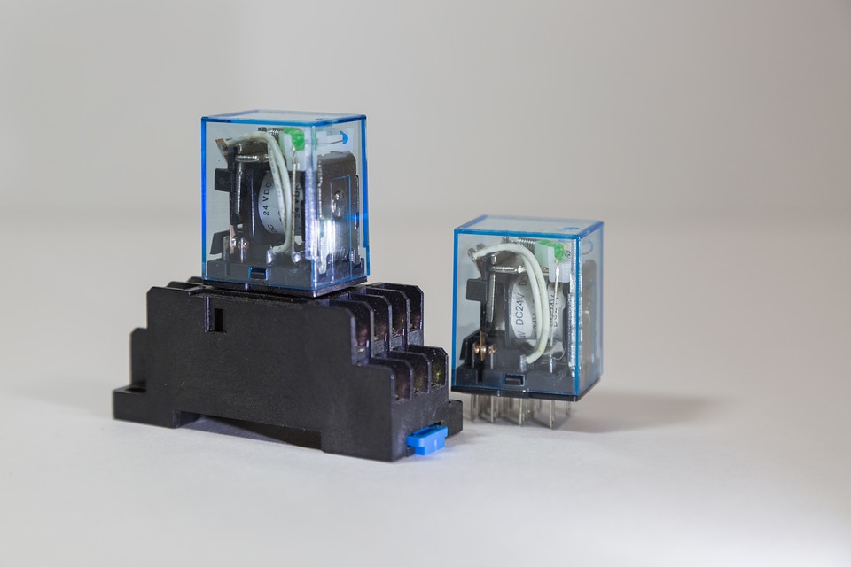
The relay or relè is a component that serves to allow the passage or not of a larger electrical quantity using a much smaller signal, it consists of one or more contacts (exchanges) controlled by a coil, which, crossed by a current, creates an electromagnetic field that attracts the contact or not, the crossing of the coil by an adequate current determines the closure of the contact and therefore the passage of current through it (larger electrical quantity), while the opening (no current in the coil) interrupts its passage.
The VDR are components that serve to limit overvoltages that could damage the electrical and electronic circuits, they are comparable to arresters and exist for various operating voltages.
Switches and electric diverters are simple manually operated contacts which interrupt the flow of current or divert its path.
Quartz are component that use the piezoelectric property of quartz crystal, if we apply an electrical voltage to a piezoelectric material they shrink or expand in a way directly proportional to the applied voltage, if instead we apply a pressure to its ends a directly proportional voltage is established to the applied pressure, the quartzes are used in high frequency to fix the oscillation frequency of the oscillators, or more generally to make pressure transducers. To find out more, consult the radiowave page of this site.
if you want to know more or need professional advice, you can contact me via the Contact page.
Following a series of images that will allow you to better recognize the components just treated, click on the images to enlarge them and view them better.
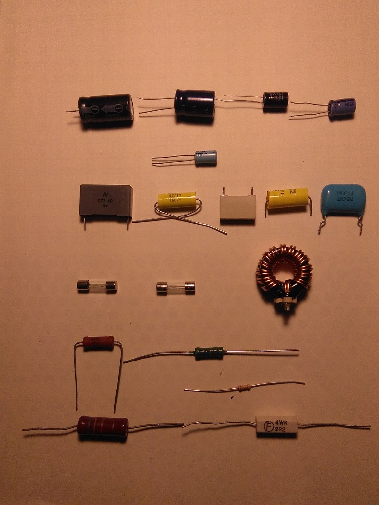
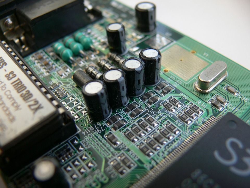
Various passive components Inductors, solid electrolytic capacitors
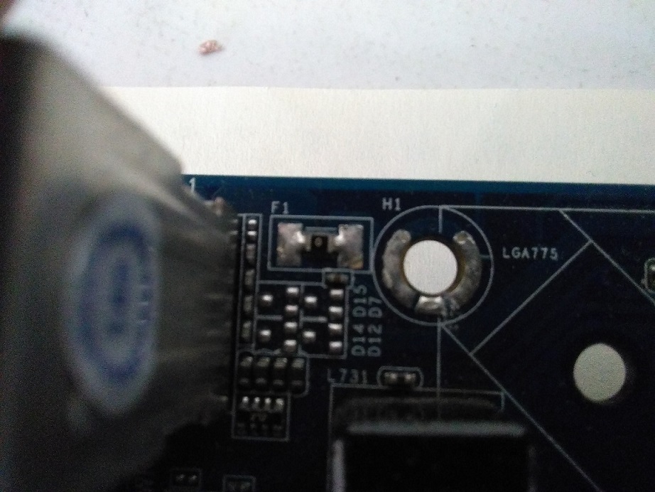
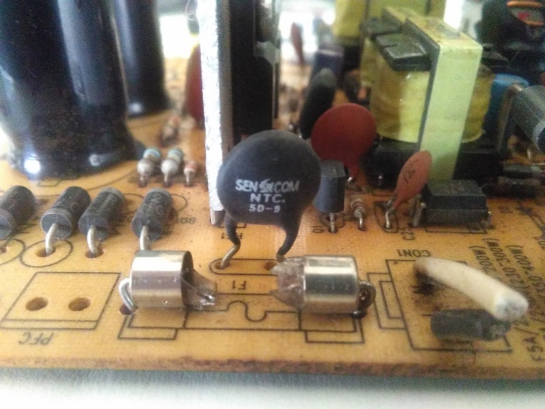
SMD micro fuse NTC resistor and damaged fuse
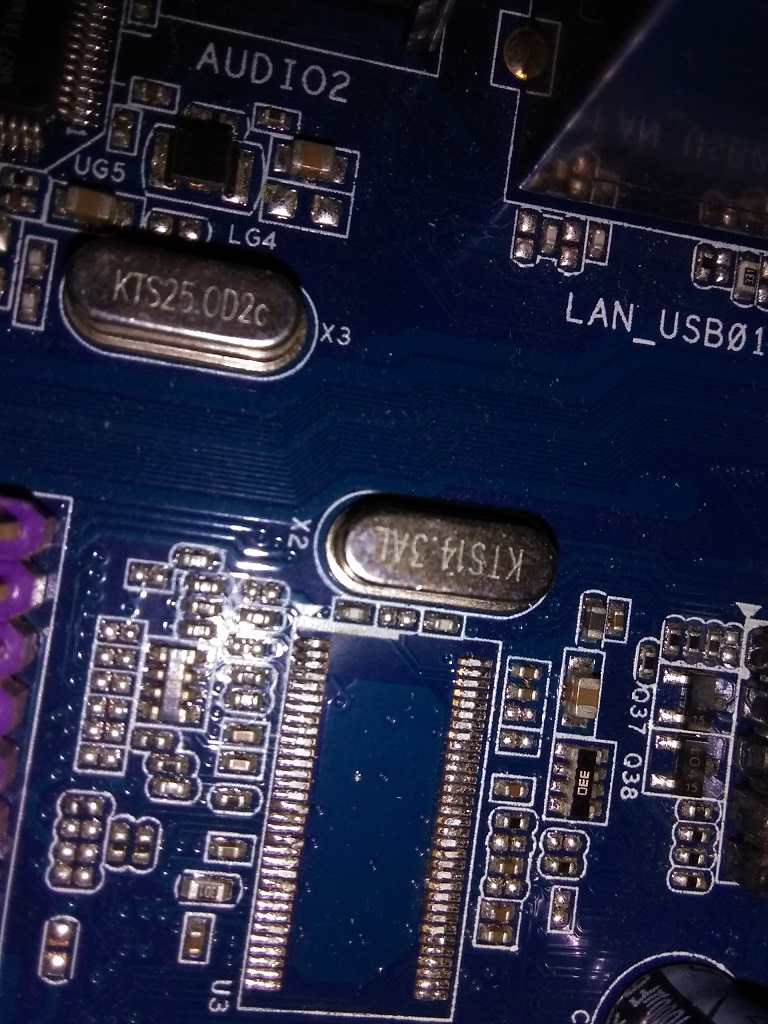
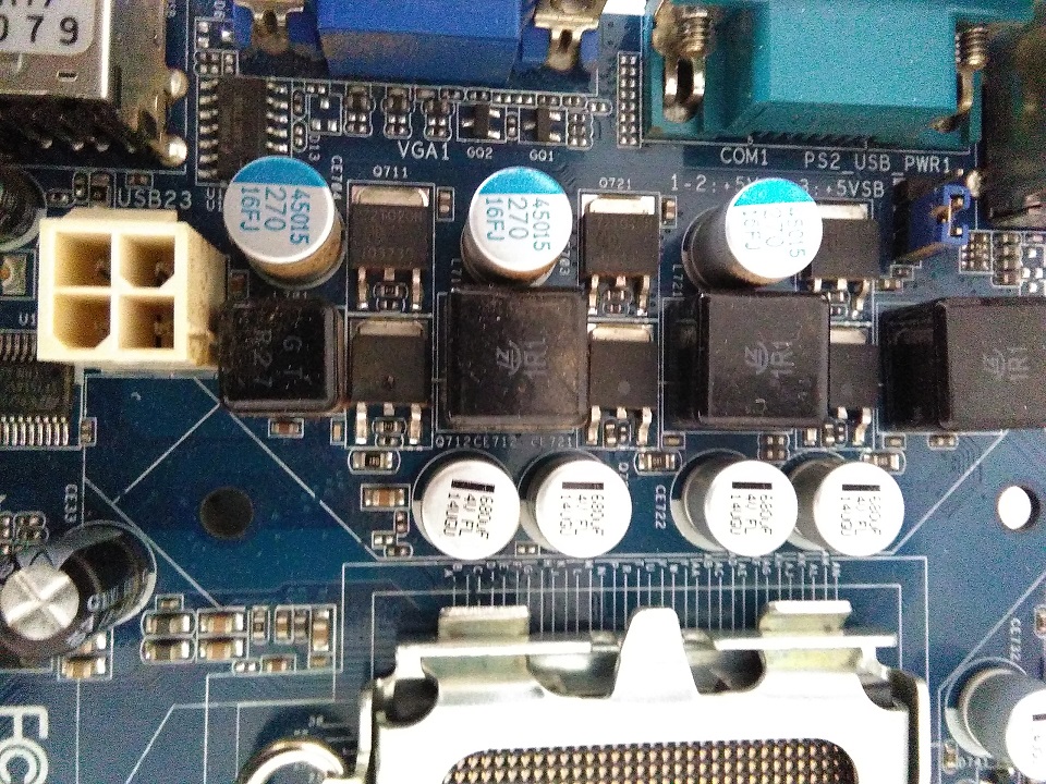
Quartz Inductances (green), SMD capacitors and resistors
Of course it is impossible to condense all these concepts in a small space, mine wants to be only a good guide for those who look out on this fantastic world, it is possible however to deepen or request a professional consultation by contacting me, for this go to the contact page.
Thank you for visiting my website and following my guide, come back to visit it in the future.
Informatics, Software and O.S., Computer network
Electronics, Active components, passive components
Radiowave
Seismo
Contacts
Who I am
Sitemap
Audio
Terms of use
Armando Caligiuri, Electronic senior expert, electronic and I.T. maintainer, I.T. consultant
Web master Armando Caligiuri
(C) 2024 V3.2